
This newer-shape Kärcher HDS 5/11 UX came through our workshop for a new heating coil, control piston and seals, with the valves rechecked while the machine was apart. It was a fairly recent machine and did not need a wholesale rebuild. This is the hose-reel version: an uncommon find in our used stock, and a particularly tidy, compact hot-water machine.
Below, our own photographs show the machine assembled, with its outer cover removed, the exposed replacement coil, and the connections underneath the boiler. We explain the access stages, what needs protecting during the job, and why the pump work is separate from changing the coil.
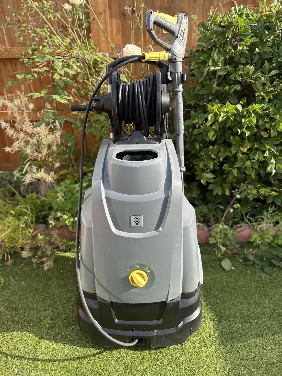
What we changed on this HDS 5/11 UX
- Heating coil: replaced with a new coil.
- Control piston: replaced.
- Seals: renewed as part of the repair.
- Valves: rechecked, rather than automatically replacing every valve.
A relatively new machine can still need individual parts. That does not mean the motor, complete pump or every component in the burner needs replacing. The sensible repair is to identify the affected assemblies, inspect what has been disturbed and retain serviceable parts. Here, the work centred on the coil and the pressure-control/sealing components.
The photographs document access and the replacement, not a pressure-test certificate. They also do not establish why the original coil needed replacing. Freeze damage, corrosion and other possible causes should not be assumed from an outside photograph.
1. Identify the machine and prepare the work area
Record the complete Kärcher product number and serial number before ordering. “HDS 5/11” alone is not enough to guarantee the right coil, control piston or seal kit. Compare the applicable parts drawing, connection arrangement and supplied replacement before starting; do not force a similar-looking part to fit.
Work on a stable, clean surface with space to support removed assemblies. Have labelled trays for screws, clean caps for open water connections, suitable fuel containment and properly rated lifting assistance ready. Photograph wiring, hose routes and brackets before disturbing them. The garden photographs show the machine and access clearly; they are not a recommendation to open a pump on grass.
2. Remove the outer cover, then decide how much access is needed
There are three different tasks here: removing the cosmetic hood, opening up the back around the boiler, and separating the upper assembly to reach the pump. Taking off the front cover does not mean the coil is ready to lift out.
The older manual releases the hood latch from above with a screwdriver. Rear access involves the handle, clipped reel connection, reel and rear panel. Temporarily remove the tank cap for panel clearance, then replace it. Check the newer machine’s retainers first.
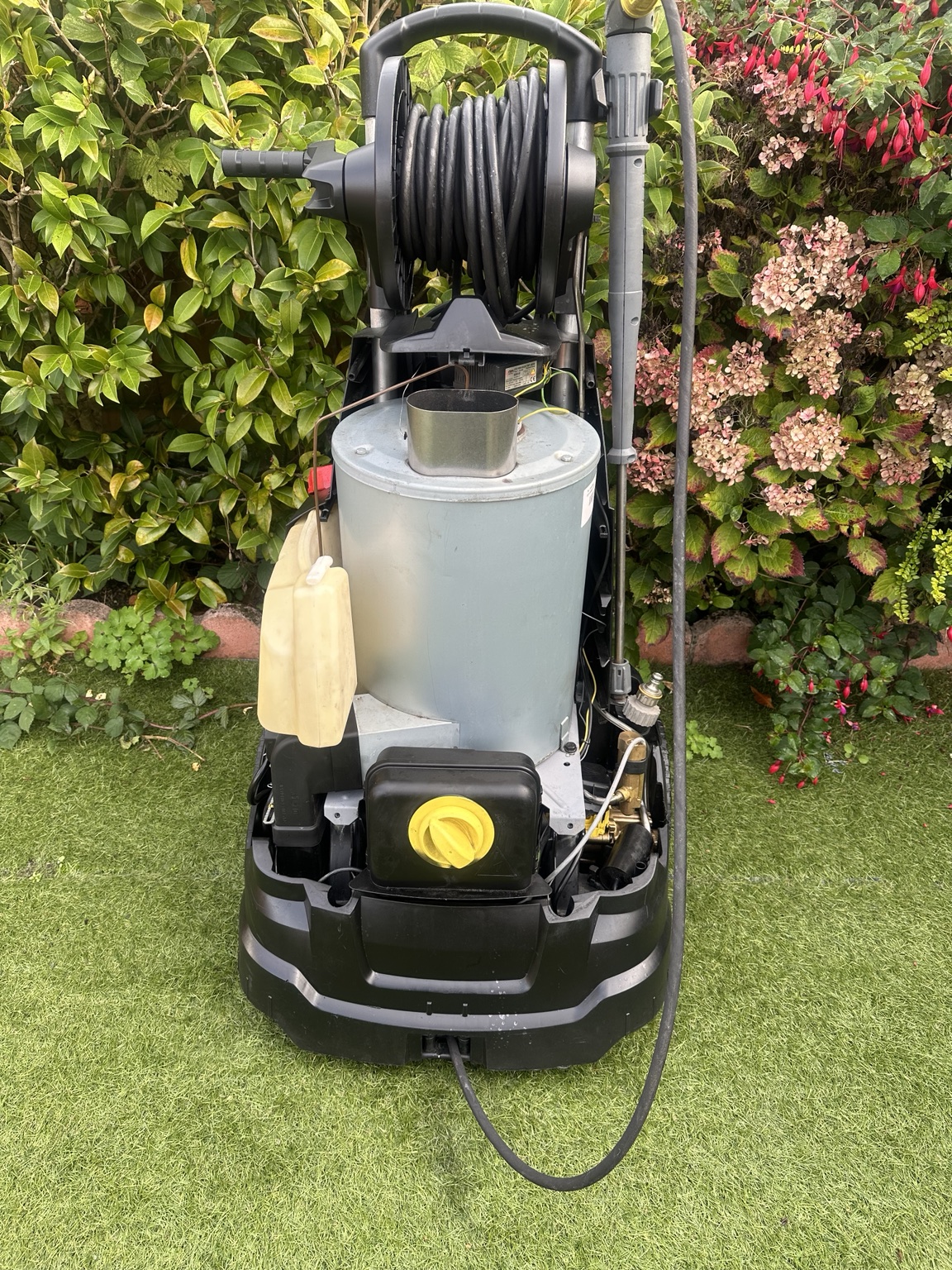
Keep track of different screw lengths and support plastic panels as their final fixings are released. If a cover catches, stop and look for a remaining fastener or hose rather than bending it. Put the reel where its fittings cannot be knocked or contaminated; a damaged reel connection creates another high-pressure leak to repair.
3. Identify the connections underneath the boiler
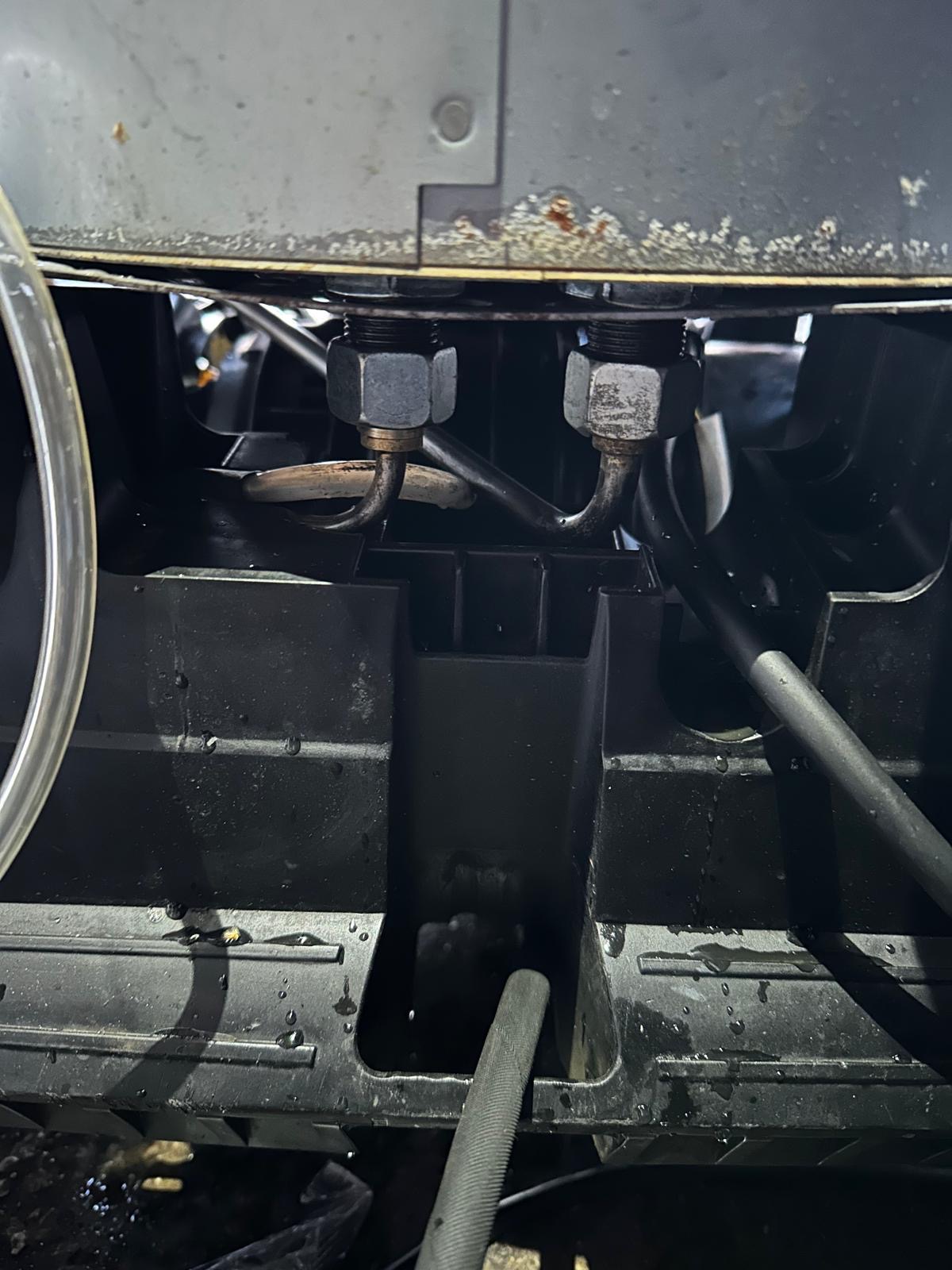
This is an important area to photograph before taking anything apart. Trace and label the water connections so that their original routing is preserved. The image shows why access matters: the pipe bends and surrounding chassis leave limited space for a tool.
With the machine cold, isolated and depressurised, support the stationary fitting while undoing its mating union with the correctly fitting tools. Do not let the pipe absorb the twisting force. Collect residual water and protect open ends from dirt. A seized fitting is a reason to reassess access and repair technique, not to use the coil tube as a lever.
We have deliberately not given a universal spanner size or tightening torque. Neither can be established from this photograph, and values from a larger HDS 745 or 7/10 should not be carried across to this compact machine.
4. Expose and remove the coil with the assembly supported
The manual separates coil access from upper-assembly removal for pump work. Pump access includes fuel isolation, sensor, earth, ignition, detergent and safety-block disconnections, followed by heater-base and temperature-control release. Follow its illustrated sequence, not this summary alone.
Before releasing any load-bearing retainer, establish what it supports. Identify every pipe, bracket, cable and sensor still attached to the assembly being moved. Support it with suitable equipment, keep fingers clear of trapping points and never lift by a water tube, wire or fuel hose. If it will not move freely, find the remaining attachment rather than pulling harder.
Keep the burner components, insulation and casing in their recorded orientation. Do not bend delicate sensing components, crush wiring, disturb burner adjustments unnecessarily or break insulation away to gain clearance. Damaged heat-resistant parts need the correct replacement; ordinary sealant is not a substitute.
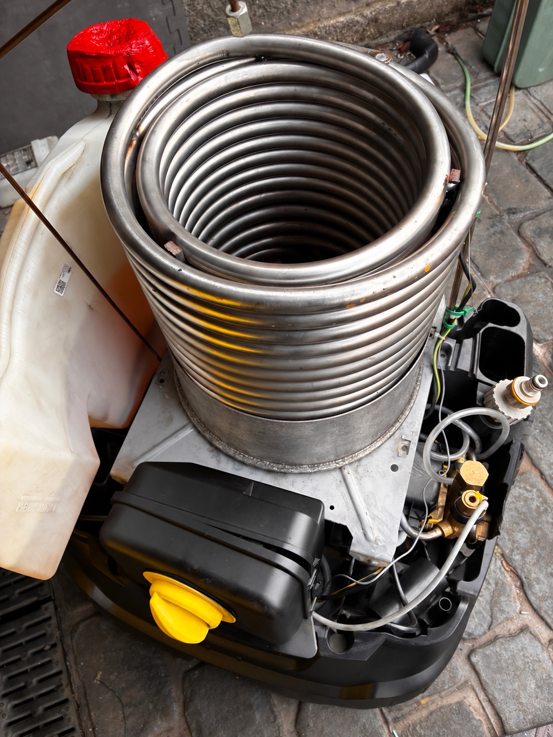
Before installation, check the replacement against the machine-specific parts information and original assembly: mounting arrangement, water connections and clearances must all agree. Inspect the supporting structure and heat-resistant insulation. Clean loose debris without driving it into open water passages or damaging the insulation.
Lower and locate the supported replacement without loading its pipes sideways. The connected pipework should meet naturally, not need pulling into place with the union nuts. Replace the specified disturbed seals, secure the approved retaining hardware and use the correct service tightening data. The photo is an in-progress view: the machine must not be fired in this exposed state.
5. Control piston, seals and valve checks
Alongside the coil replacement, we changed the control piston and seals and rechecked the valves. These are water-side repairs; fitting a new heating coil does not by itself resolve a sticking control component or an internal sealing fault.
The manual treats control-piston removal as a separate repair and specifies supporting the piston housing during head removal. Consult the procedure before undoing bolts.
Keep the small components in order
As a general pump-repair precaution, document the orientation of seals, guides, springs and spacers before removal and compare it with the correct exploded drawing. “It fits in the hole” is not proof that a component belongs on that side of the housing. The four photographs here do not show the internal piston assembly, so they should not be used as an assembly-order reference.
Inspect the bore and seating surfaces for dirt, damage or corrosion. Use only the lubricant specified for the relevant seal and component. Do not force a binding new piston into service, scratch a sealing surface with a sharp tool or tighten the housing to overcome incorrect assembly.
Rechecking valves is different from replacing them
During valve inspection, look for contamination, damaged seating faces and damaged or displaced sealing parts. Keep each assembly and its orientation identifiable. A visual check alone cannot establish that a valve seals correctly under working pressure; performance must be assessed during a controlled test. Our repair record is that the valves were rechecked, not that an entire new valve set was fitted.
6. Reassemble carefully and test the water side first
Before reconnecting power, account for all tools and loose parts. Check every disturbed connection against the disassembly photographs, verify protective-earth continuity and electrical safety as appropriate, and check that cables and hoses cannot rub, pinch or touch hot surfaces. Restore all guards and protective components required for testing.
The following is a commissioning checklist, not a claim that these photographs record measured results:
- Water supply and priming: establish an adequate clean supply and follow the operating instructions to clear air. Do not run the pump dry.
- Cold operation: a competent technician checks output, disturbed unions and pump seals under controlled conditions. Never search for a high-pressure leak with a hand.
- Trigger response: check normal stopping and restarting, and investigate repeated cycling or pressure loss rather than masking it by adjustment.
- Fuel and hot operation: only after the water-side and safety checks pass, check fuel tightness, burner operation and temperature control in an appropriately ventilated test area.
- Final inspection: after cooling and isolation, inspect for seepage, displaced hoses and loose fixings before returning the machine to use.
Stop for unexpected smoke, a fuel smell or leak, electrical tripping, water near electrics, unstable pressure or abnormal heat. Do not keep restarting to see whether a fault clears. Burner setup requires suitable instruments and model-specific service information, not adjustment by flame colour or guesswork.
Why this was a targeted repair rather than a complete rebuild
This was a fairly new, clean machine, so the repair did not call for replacing everything inside it. The new coil, control piston and seals addressed the work required, with valve checks alongside. The newer body shape and integrated hose reel make this particular UX a nice example to document: useful photographs of a real repair, rather than a generic diagram of a different HDS model.
Reference: the older HDS 5/11 U/UX service manual
Reference: Kärcher’s HDS 5/11 U/UX service manual, 5.906-487.0, revision 00 (April 2010): sections 4.5 (hood), 5.9–5.11 (pump access), 6.1–6.3 (rear and reel). Do not assume older fittings or settings match this newer machine. Obtain current service data using its product and serial numbers. All photographs here are ours.
Need an HDS 5/11 coil or pump repair? Send us the model plate and symptoms →
Related guide: why a Kärcher HDS keeps switching on and off →
Send the model and symptoms, or ask us to help match a machine to the work.